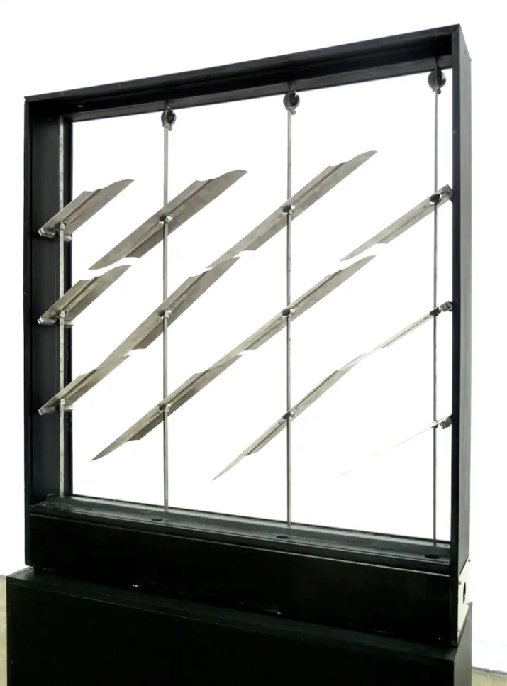
Bimetal Facade System
Team: Professor Brad Bell, Adam Heisserer, Alexei Dukov, Khang Nguyen, and Tenaj Pinder.
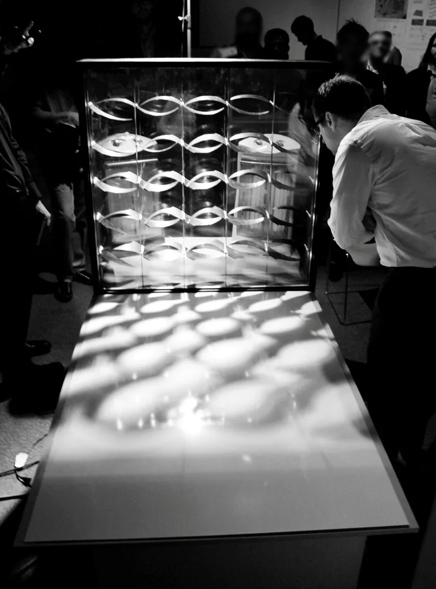
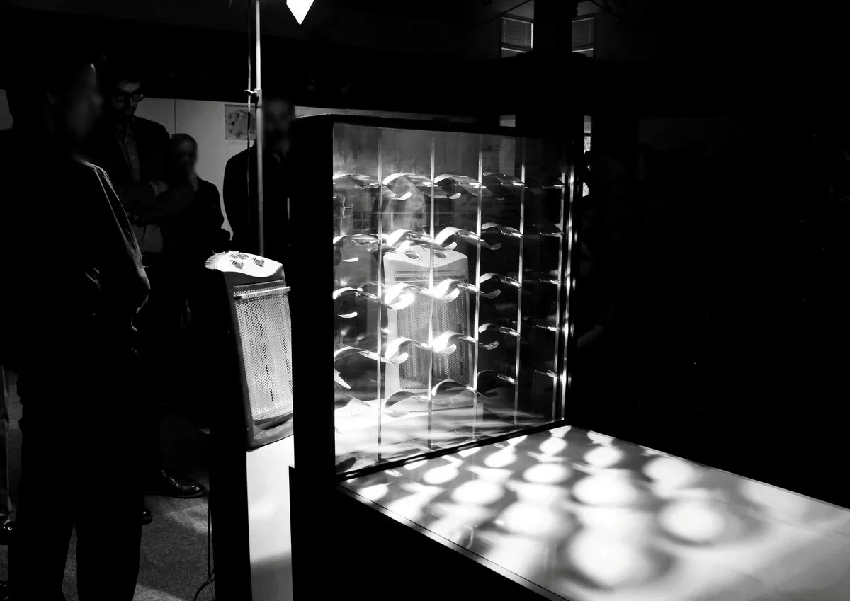
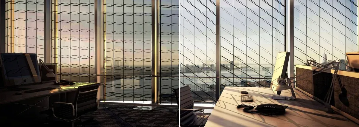
The building envelope consolidates a number of contradictory performance criteria. (Maximize views while minimizing heat transfer. Allow heat gain during cold weather, and avoid it during warm weather). Traditionally, these issues have been met with static facade systems because moving parts require additional energy and are prone to mechanical failure. These challenges can be overcome by embedding the needed responsiveness in the material itself. A thermally activated bimetal surface placed within two panels of insulated glass can be designed to block sunlight when necessary, with no added operational energy or digital technology.
This facade prototype was developed as part of the UT Arlington Digital Architecture Research Consortium between 2013-2014 with Professor Brad Bell, Adam Heisserer, Alexei Dukov, Khang Nguyen, and Tenaj Pinder.
Prototype 1.0
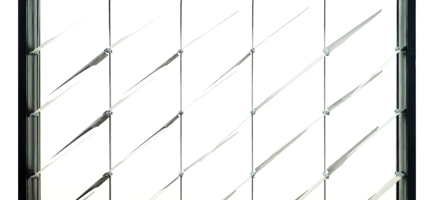
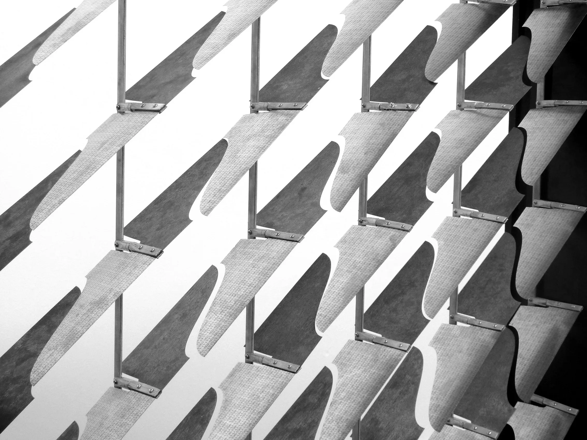
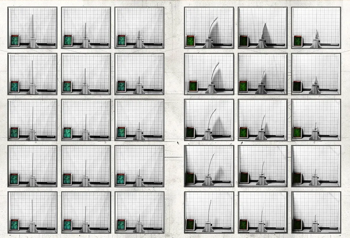
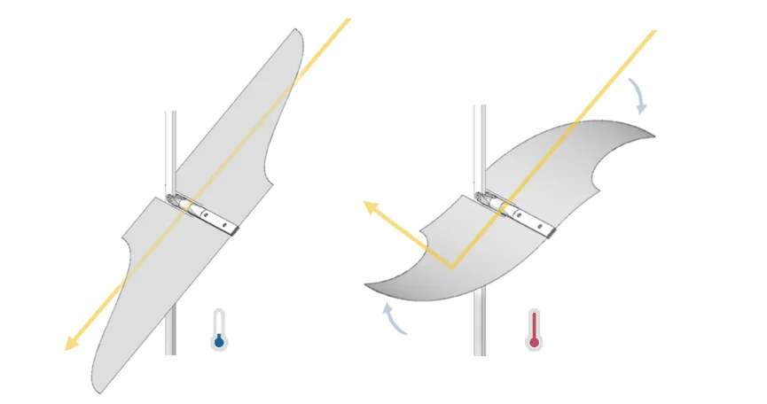
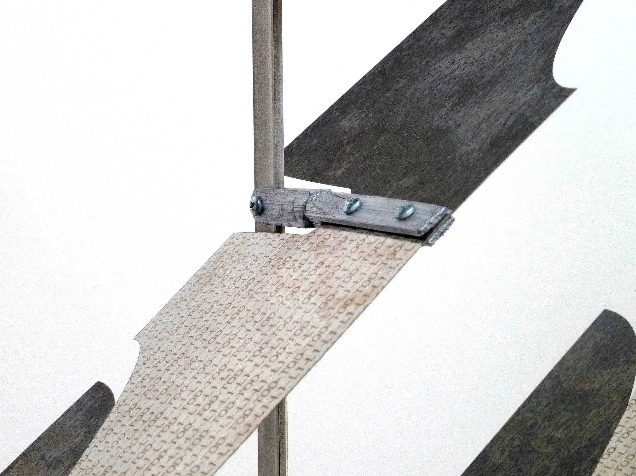
The first prototypes were built with thermally active bimetal that bends when exposed to direct sunlight. The bimetal is composed of two layers of metal that expand at different rates when heated.
Fixed to a 3D printed joint, the metal fins remain unbent and parallel at room temperature, and curl into a more horizontal position when heated. On a south-facing facade, this allows for more solar heat gain from low-angle morning or winter sun when temperatures are typically colder, while preventing solar heat gain from high-angle mid-day or summer sun when temperatures are typically warmer.
The fins bend on the axis perpendicular to the glass to maintain exterior views. A drawback of other bimetal shutter systems is that views are sacrificed when the system is active.
Prototype 2.0
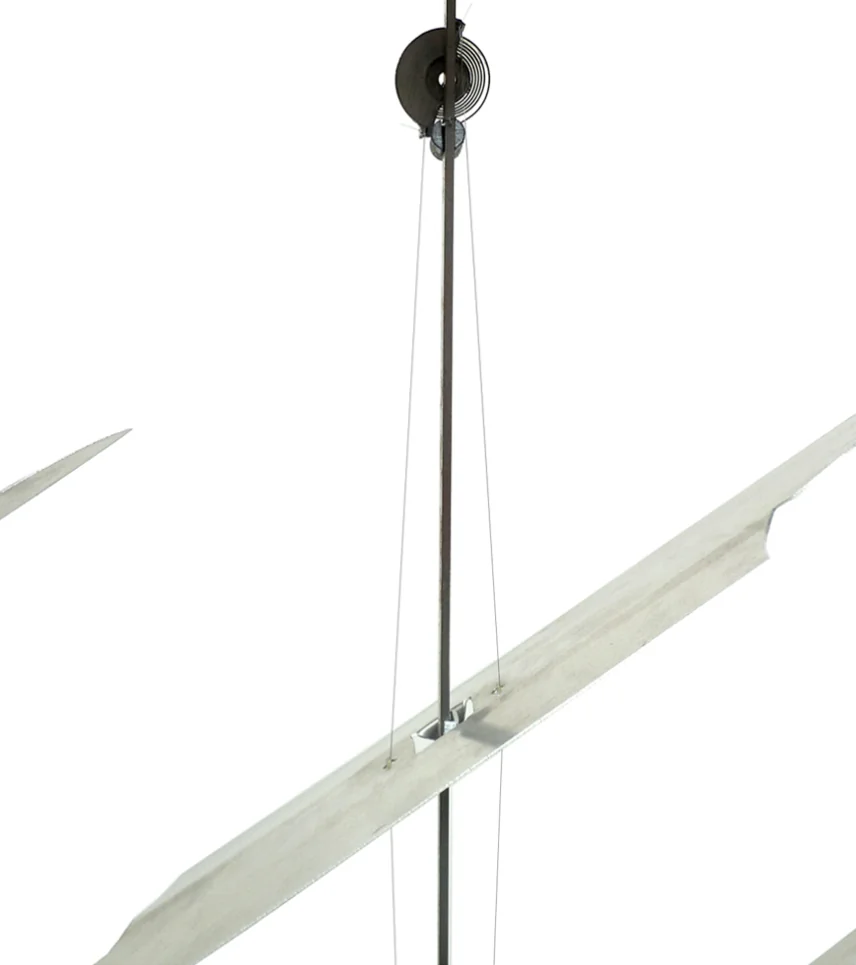
The following prototypes improved the rotational ability of the system by using bimetal coils to actuate the system rather than bimetal fins. This allows the fins, now a non-bending component, to be made from a thin-gauge aluminum cut with a CNC mill. They are rotated by a wire suspended from the coil at the top of each column of fins. This allows about 70 degrees of rotation, an improvement from the previous prototype.
Prototype 3.0
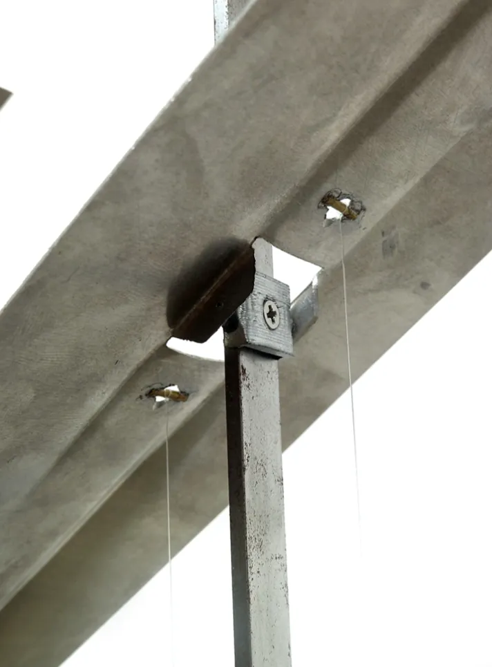
In this iteration, the wire is wound continuously from a disk attached to the center of the bimetal coil, to a disk attached to the center of the aluminum fin. With a higher gear ratio, the fins rotate more actively and consistently.
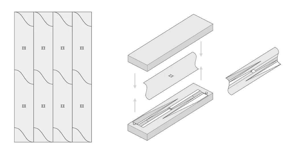
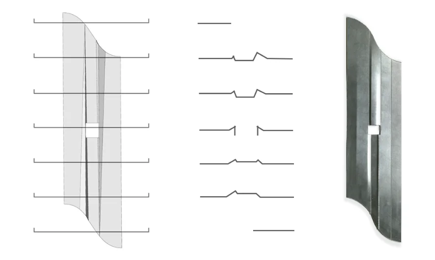
The aluminum fins are cut flat, and then pressed in a wooden mold to create indentions along the center of the fin. They can then rotate to a more vertical position without colliding with the vertical support. The ridges along the length of the fin also provide rigidity, allowing them to be made from thinner aluminum.
Prototype 4.0
This prototype excludes any wire or vertical support in order to decrease points of failure and increase visual transparency. One end of a central axis is adhered to the glass itself, creating a thermal bridge to the bimetal coil that directly rotates the fin when heated. The drawback of this system is the difficulty of calibrating the desired rotation to the temperature, and the misalignment of the fins.